Basics of the ARM Architecture
ARM Architecture
The initials ARM, which are an acronym for Acorn RISC Machine, were subsequently shortened to Advanced RISC Machine. The ARM architecture family is used in most smartphones, tablets, and embedded systems, as well as some laptops, because it uses less energy and costs less.
The main business of ARM is to sell IP cores, i.e., they
provide to all licensees an integratable hardware description of the ARM core as well as complete software development toolset (compiler, debugger, software development kit) and the right to sell manufactured silicon containing the ARM CPU.
Source: Wikipedia.
There are two types of RISC architectures: 32-bit (ARMv1 to ARMv7) and 64-bit (ARMv8).
The ARM architecture is a load/store architecture that generally requires aligned memory accesses. There is a uniform register file consisting of 16 32-bit registers or 32 64-bit registers.
It has a fixed instruction width, which makes it better at decoding and pipelining, but the code density is lower. However, a 16-bit instruction set was introduced later (called Thumb).
Most instructions can be executed in one clock cycle and can be executed on specific condition codes. Arithmetic instructions only change condition codes when they are asked to. A barrel shifter works with most arithmetic instructions and address computations.
The ARM architecture supports many different modes:
- User mode: it’s a non-privileged mode similar to Intel’s ring 3.
- IRQ mode: it’s privileged mode use to handle interrupts.
- FIQ mode: it’s privileged mode use to handle Fast Interrupt Request (FIQ) interrupts.
- Supervisor mode: it’s privileged mode similar to Intel’s ring 0 entered whenever the CPU is reset or when an
SVCinstruction is executed.
Other CPU modes include the abort mode, the undefined mode, the system mode, the monitor mode, the hypervisor mode, etc.
Modes and Registers
32-Bit ARM
On 32-bit ARM, the registers R0 through R7 are common to all CPU modes. Registers R8 through R12 are the same across all CPU modes, except FIQ mode: this mode has its own unique registers R8 through R12.
Each mode that can be entered due to an exception has its own R13 and R14. These registers generally contain the stack pointer and the return address from function calls, respectively.
R13 is also called SP (Stack Pointer). R14 is called LR (Link Register). It holds the address to return to after a function call completes. R15 is also called PC (Program Counter). It holds the address of the next instruction to be executed. Finally, CPSR is a 32-bit register that holds flags (Current Program Status Register).
64-Bit ARM
On 64-bit ARM, there are 31 general-purpose registers 64-bit X0-X30, or 32-bit W0-W30. There is a separate set of 32 128-bit registers for floating-point and vector operations (V0-V31).
The program counter PC and the stack pointer SP are not general-purpose registers. X30 is also called LR (Link Register). LR is a special place that stores information about where a function should return to after it has finished. X29 is called FP (Frame Pointer).
There is no CPSR register in 64-bit ARM; instead, flags are accessed as Processor State fields that can be read and written using the MRS and MSR system instructions.
Instructions
On a RISC architecture such as ARM, incrementing a counter stored in memory typically requires three instructions: a first to read the data from memory into a register, a second to increment the value in the register, and a third to store the data from the register into memory.
In 32-bit instruction sets, almost every ARM instruction has a conditional execution feature called predication. Predication is a way to decide whether to execute an instruction based on the result of a calculation. This is done with a 4-bit condition code selector, also called a predicate. To allow unconditional execution, one of the four-bit codes always causes the instruction to be executed. The 64-bit instruction set introduced in ARMv8-A replaced conditional execution with conditional selection instructions.
Important ARM instructions include:
- Data moving instructions:
MOV,LDR,LDM,STM,STR, … - Arithmetic and Boolean instructions:
ADD,SUB,MUL,AND,OR,EOR,ORN, … - Stack- and subroutine-related instructions:
PUSH,POP,BL, BX, … - Control-flow-related instructions:
CMP,TST,B, … - in addition to system-, vector-, security-related instructions, etc.
Condition Codes and Barrel Shifter
This is in contrast to most other CPU designs, that have condition codes only on branch instructions (for example, Intel's Jcc).
As an illustration, you can look at the following C code implementing the GCD algorithm documented on Wikipedia:
int gcd(int a, int b) {
  while (a != b)  // We enter the loop when
                  // a < b or a > b, but not when a == b
    if (a > b)    // When a > b we do this
      a -= b;
    else          // When a < b we do that (no "if (a < b)"
                  // needed since a != b is checked
                  // in while condition)
      b -= a;
  return a;
}
This code can be rewritten to be more like ARM instructions:
loop:
    // Compare a and b
    GT = a > b;
    LT = a < b;
    NE = a != b;

    // Perform operations based on flag results
    if (GT) a -= b;    // Subtract *only* if greater-than
    if (LT) b -= a;    // Subtract *only* if less-than
    if (NE) goto loop; // Loop *only* if compared values were not equal
    return a;
Finally, the corresponding ARM instructions are:
; assign a to register r0, b to r1
loop:   CMP    r0, r1       ; set condition "NE" if (a ≠ b),
                            ;               "GT" if (a > b),
                            ;            or "LT" if (a < b)
        SUBGT  r0, r0, r1   ; if "GT" (Greater Than), then a = a − b
        SUBLT  r1, r1, r0   ; if "LT" (Less    Than), then b = b − a
        BNE  loop           ; if "NE" (Not Equal), then loop
        B    lr             ; return
As mentioned above, one can use the barrel shifter to write operations such as
a += (j << 2); as a single ARM instruction:
ADD Ra, Ra, Rj, LSL #2Thumb / Thumb-2 / NEON
The Thumb instruction set is a compact 16-bit encoding for a subset of the ARM instruction set. Here's the idea: if one reduces some of the functions, one can make the code more compact and save memory. Only branches can be conditional. Also, many opcodes can only access half of the CPU's general-purpose registers.
Thumb-2 adds selected 32-bit instructions to Thumb, extending the instruction set with new features: bit-field manipulations, table branches and conditional execution.
The NEON extension is a combined 64- and 128-bit SIMD instruction set. It provides a way to speed up media and signal processing applications.
Subroutine Call
The ARM and Thumb instruction sets both contain a basic subroutine call instruction, BL, which performs a branch-with-link operation. The effect of executing BL is to transfer the sequentially next value of the program counter (the return address) into the link register LR and the destination address into the program counter PC.
The bit 0 of the link register will be set to 1 if the BL instruction was executed from Thumb state, and to 0 otherwise.
The result is that control is transferred to the destination address.
Control-Flow
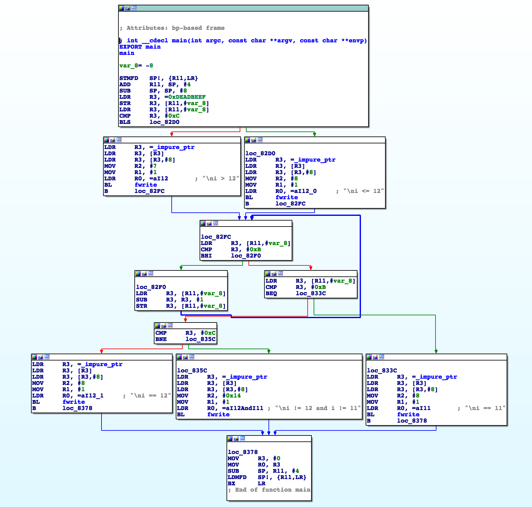
For the sake of comparison, here is the C code of Episode #4:
#include <stdio.h>

int main(void)
{
  unsigned int i = 0xDEADBEEFUL;

  if (i > 12) {
    fprintf(stdout, "\ni > 12");
  } else {
  fprintf(stdout, "\ni <= 12");
  }

  while (i >= 12) { i--; }

  switch (i) {
  case 12:
    fprintf(stdout, "\ni == 12");
    break;
  case 11:
    fprintf(stdout, "\ni == 11");
    goto label;
  default:
    fprintf(stdout, "\ni != 12 and i != 11");
  }

label:
  return 0;
}
The IDA Pro disassembler produces the following result:
In the next episode, I will cover calling conventions. Stay tuned!
Thanks for reading Crumbs of Cybersecurity! Subscribe for free to receive new posts and support my work.